Stop Litigation Expert Abuse

In an episode of the TV series The Sopranos, Carmela Soprano discovers that she is unable to retain a competent lawyer for her divorce proceedings, apparently due to her husband Tony having contacted a number of them in advance, ostensibly for advice on unrelated matters. In so doing, Tony deviously “polluted the attorneys” by creating a conflict of interest for them.

It would seem that some law firms may be incorporating this questionable practice into their strategy of obtaining subject matter experts and expert witnesses for high-profile litigation. Apparently, their strategy involves interviewing a large number of known experts, through a broker, requiring the candidates to agree to non-disclosure during the initial email contacts, and then rejecting them as candidates, often cutting off all further communications.

By doing this, the experts are then precluded from being retained by the opposing party, due to a “restrictive covenant” in the original email communication, with no confidential information having been exchanged, and with no compensation for their acquiescence.  Essentially, the expert has provided value to the broker and law firm (exclusivity), in return for nothing.

I can describe my own experience in these matters. I was approached to consult as a subject matter expert for a number of very-high profile cases, and each time, I was directed to agree to a “confidentiality agreement” before I was interviewed for suitability. Objectively, it appeared that I was one of very few people who was an extremely good match to a very specific — and narrow — set of experience requirements. Nonetheless, I was rejected, after responding to an email containing a restrictive covenant, with no further communication at all.

Lest the reader conclude that I simply was rejected as non-qualified, I can point to the fact that, in several instances, all communication ceased after I solicited a sample NDA, without having mentioned compensation or any other conditions.  It would seem there is something unreasonable going on here.

The solution to expert-pool contamination requires a willingness by all parties to accept responsibility.

  • Experts: When considering retention as a subject matter expert, insist on a written NDA, and consider one whose execution requires an initial non-refundable retention payment to you (you can always apply it to the initial consulting time, if retained). Be sure to scrutinize the language of the initial contact emails, and specifically disagree with any language that requires confidentiality without a formal agreement.
  • Law firms: First of all, refrain from this behavior, which is at best unethical. Considering the fact that you may be on the losing end of such a situation, it’s in the best interest of the profession as a whole to avoid a “mutually assured destruction” mindset.  Look to include, rather than exclude, talent.  It’s not too expensive to build a contingent of experts on a retainer, so that you can pick and choose the right one as needed; plus, it’s insurance against illness and other contingencies. Employers customarily reimburse candidates for travel expenses to a job interview, so it should not be considered unusual to compensate an expert at the very least for a telephone (or in-person) interview, especially if it’s in return for exclusivity.
  • Brokers:  Your biggest asset is your talent base — don’t blow it by agreeing to a shady practice that will eventually hurt you.  Don’t forget, you need a good supply as much as you need an ongoing demand.

–agc

ATSC 3.0 Announcements at CES 2019

With the ATSC 3.0 standard essentially finished last year, the casual observer might have expected to see new product at this year’s CES Show in Las Vegas.

Indeed, while there were a few 3.0 TVs scattered about – including at invitation-only showings by well-known TV manufacturers at suites and hotels – they were only early prototypes, since we shouldn’t expect to see real product announcements until the 2020 show – which just happens to be when broadcasters have said they will crank up transmissions using the new standard.

Echoing this at the show was the VP of Communications at LG, John Taylor, who said, “We expect that the launch pad is really 2020,” which is consistent with the typical 18 to 24 month silicon design cycle for chips to follow a new standard.

ATSC 3.0 Software Stack

ATSC 3.0 is, of course, the latest version of the Advanced Television Systems Committee (ATSC) standard. It will support several advances including mobile viewing, 3D television, 4K Ultra High Definition (UHD), high dynamic range (HDR), high frame rate (HFR), and wide color gamut (WCG) picture quality, as well as immersive audio and interactivity.

Until we see those new products emerge, the news we’re more likely to see will be from broadcasters.


Industry Leaders Collaborate to Launch ATSC 3.0 Chip for Broadcast and Mobile Applications

ONE Media LLC, a subsidiary of Sinclair Broadcast Group, and India’s Saankhya Labs, together with VeriSilicon and Samsung Foundry, announced at CES the successful launch of an advanced multi-standard demodulator System-on-a-Chip (SoC) supporting the ATSC 3.0 standard.

The universal demodulator chip is based on Saankhya’s patented Software Defined Radio Platform, and supports 12 DTV standards including ATSC 3.0, DVB-T2, ISDB-T, and satellite and cable standards for TV, set-top boxes, and home gateways, as well for automotive and mobile applications.

This announcement follows Sinclair Broadcast Group’s recent commitment to a nationwide roll-out of ATSC 3.0 service and its past announcement to fund millions of chipset giveaways for wireless operators.

Two variants of the chip were announced: a “Demod-only” variant, SL3000, is designed for TV applications such as in HDTV sets, Set-top Boxes (STB) and home gateways. A “Demod-plus” Tuner variant, SL4000, is designed for mobile and portable devices, possibly making it the world’s first mobile-ready ATSC 3.0 chip. The mobile device is targeted to accelerate the adoption of the ATSC 3.0 standard across markets with both Direct-To-Mobile TV capabilities and Broadcast/Broadband convergence solutions.

The demodulator SoC was designed and developed by Saankhya Labs with ASIC turnkey design and manufacturing services from VeriSilicon, using Samsung Foundry’s state-of-the-art 28FDS (Fully Depleted SOI) process technology), chosen for its low-power capabilities.

Mark Aitken, President of ONE Media 3.0, said,

These mobile 3.0 chips validate the ‘sea change’ in over-the-air distribution of not only television, but all digital data. Broadcasters are doing their part by deploying the NextGen transmission facilities, and now there will be devices enabled to receive that data, personalized and in mobile form. This chip is the key to that disruptive future in a 5G world.”


Broadcasters and Mobile Operators Partner to Deploy ATSC 3.0 – Harman Separately Partnering in Mobile Applications

SK Telecom and Sinclair Broadcast Group announced in Las Vegas that the companies signed a joint venture agreement to lead next-generation broadcasting solutions market in the U.S. and globally. The two companies will jointly fund and manage a joint venture company within the first quarter of this year. The joint venture company will develop innovative broadcasting solutions based on ATSC 3.0.

The commercialization of broadcasting solutions based on ATSC 3.0 – which enables data communications in broadcasting bands – will give rise to new services such as personalized advertisement and in-vehicle terrestrial TV broadcasting and map updates. It will also support two-way communication between broadcasting companies and user’s smartphone/vehicle/TV by recognizing user’s personal IP address.

SK Telecom and Sinclair anticipate all television broadcasting stations throughout the U.S. will adopt broadcasting solutions based on ATSC 3.0 within the next decade. Through the joint venture company, the two companies plan to actively provide ATSC 3.0 standards-based solutions to all U.S. broadcasting companies and seek other opportunities globally. The joint venture agreement follows last year’s memorandum of understanding (MOU) signed between SK Telecom and Sinclair at CES 2018 to jointly develop leading technology for ATSC 3.0 broadcasting.

Separately, the two companies also announced at the 2019 CES Show that they signed a Memorandum of Understanding (MoU) with Harman International, a subsidiary of Samsung, to jointly develop and commercialize digital broadcasting network-based automotive electronics technology for global markets.

The companies intend to unveil their automotive platform and related equipment and services for the first time at the 2019 National Association of Broadcasters Show (NAB Show) in Las Vegas in April 2019.

— agc

Why You Should Run Out and See “2001: A Space Odyssey,” Again

The landmark film is being re-released in select U.S. theaters this month, to mark the 50th anniversary of Stanley Kubrick’s science fiction blockbuster.

You should go see it, either again, or for the first time.

First of all, it’s an artistic masterpiece that stands up well, even after five decades of cinema technology advancement.  And the story, at the very least, is thought-provoking.  Never mind that the allegory is at times radical, to say the least.

But there’s a technical reason to go see it in a theater: if you’ve only seen it on a video display in your home, you’re missing out on the way Kubrick captured the images.  This is because the film was shot in Super Panavision 70, which uses a 65 mm negative, and spherical lenses, to create an aspect ratio of 2.20:1.

Since your “puny” HDTV at home has an aspect ratio of 16:9 (1.78:1), this means that every electronic reproduction of the film has either been heavily cropped (at the sides), or has been  letterboxed.  The former means you’ve lost parts of the image, and the latter means you’ve lost resolution.

Plus, seeing it on a large screen in a theater completely outperforms seeing it on a little screen in your home.  And the distribution is in a clean, unretouched 70mm print.

Go see it!  In New York City, it’s playing at the Village East, May 18 – May 24.  Check your favorite website for other cities.

— agc

ATSC 3.0 Featured Prominently at 2018 NAB Conference

“The Road to ATSC 3.0: Powered by ATSC 3.0” Ribbon Cutting CeremonyDeployment of ATSC 3.0 is off and running, with a strong showing this month at this year’s NAB Conference in Las Vegas. More than 40 exhibitors and 22 technology-and-business sessions demonstrated the level of interest in the new Next Generation Broadcast TV standard, with a ribbon-cutting ceremony kicking off the activities.

ATSC President Mark Richer underscored the level of 3.0 presence at the show, saying “That’s how we know it’s real, and that’s how we know it’s happening,” and Sam Metheny, EVP/CTO at NAB, said that while ATSC is now “moving to the implementation phase,” it is a “living standard that will continue to evolve over time.” Mike Bergman, ‎Senior Director, Technology & Standards at the Consumer Technology Association, anticipates “broad deployment, and a breathtakingly immersive viewing experience,” which should complement the growing momentum of 4K TV sales.

Now that the ATSC 3.0 standard has been approved, broadcasters can develop two-way, IP-based connections with their viewers and deliver TV experiences on par with other digital media. Looking to the future, conference panelists addressed key Next Gen TV capabilities, including enhanced audience insights, addressable advertising, interactivity, and personalization, along with plans to generate incremental revenue and audience engagement.

Broadcasters are used to slow change, but now need to change faster, even on a monthly basis. The world is changing faster, and consumer demands are changing, with OTA viewership growing, and OTT services and usage growing. Mobile viewing continues to increase, a cord cutting / shaving / nevers are changing TV marketplace dynamics. On-demand viewing is an assumed feature, and digital advertising is increasingly powerful, so targeted advertising is now essential.

Chart courtesy of NAB Pilot Program

SFNs (single-frequency networks, a broadcast technology comparable to mobile cellular networks) will enable all of these new services, and data analytics will drive the opportunities. The WiFi/mobile broadband return channel defined by ATSC 3.0 means that even simple receivers need a back channel.

While MVPDs (Multichannel video programming distributors, i.e. cable and satellite) have long provided a revenue stream to broadcasters through retransmission-consent agreements, this could be one key area of the change in business model made possible by ATSC 3.0, which is not mandated by the FCC, other than at the transmission layer, and whose carriage is not currently subject to retrans obligations.

Broadcasters are interested in gathering viewership data from mobile devices and doing dynamic ad insertion. Reaching individuals will be attractive to advertisers, and broadcasters can now put movies into home boxes for Netflix, bypassing MVPDs. ATSC 3.0 is thus poised as a medium to test new business models, and broadcasters can partner with other spectrum owners and mobile carriers to supplement the “traditional” mobile spectrum.

The Phoenix Model Market project is the first collaborative single-market effort to plan for and implement a transition to next-generation over-the-air television broadcasting. Twelve stations in the Phoenix market are participating, with service testing expected to start Q2’18, and consumer service testing in Q4’18. In addition to business model testing, consumer testing will extend into 2019.

Among the consumer-facing business models to be tested are program guide & hybrid TV, personalization, and emergency alerts. On the broadcaster side, content protection, data & measurement, advanced advertising, and transition models will be evaluated.

— agc

Do I Really Need a 4K (or 8K!) TV?

The short answer is, no and yes. Some analysts will have you believe that “8K TV blows 4K away,” and that might suggest that you at least want a 4K TV.  The reality, as it comes to electronics and perception, is more complicated.

One might assume that higher resolution always makes a picture better, because the pixels get smaller and smaller, to the point where you don’t see them anymore.  But the human visual system — your eyes — has a finite capacity, and once you exceed this, any other “improvement” is wasted, because it just won’t be seen.

Here’s why (warning, geometry involved):

The term “20/20 vision” is defined as the ability to just distinguish features that subtend one-arc-minute of angle (one-sixtieth of a degree). In other words, objects at a certain distance can only be resolved as separate objects if the objects are a certain distance apart.

Using trigonometry, this works out to be about 1/32″ as the smallest separation a person with 20/20 vision can see at a distance of ten feet. We can use the same math to show that the “optimum” distance from which to observe an HD (1080-line) display (i.e., where a 20/20 observer can just resolve the pixels) is about 3 times the picture height.

On a 1080-line monitor with a 15” diagonal, this works out to an optimum viewing distance of just under two feet; with a 42” display, it’s about five-and-a-half feet. Sitting closer than this means the pixels will become visible; sitting further means that the resolution is “wasted.”  Keep in mind, also, that most people sit about 9 feet away from the TV, what is sometimes called the “Lechner distance,” after a well-known TV systems researcher.

Of course, these numbers (and others produced by various respectable organizations) are based on subjective evaluation of the human visual system, and different observers will show different results, especially when the target applications vary.  Nonetheless, the “three picture heights” rule has survived critical scrutiny for several decades, and we haven’t seen a significant deviation in practice.

At 4K, the optimum distance becomes 1.6 picture-heights: at the same 1080-display viewing distance of 5.5 feet, one needs an 84”-diagonal display (7 feet), which is already available. For these reasons, some broadcasters believe that 4K is not a practical viewing format, since displaying 4K images would require viewing at 2.5 picture-heights to match normal human visual acuity.

At 8K, the numbers become absurd for the typical viewer: 0.7 picture heights, or a 195″ diagonal (16 feet) at a 5.5-foot distance.  With a smaller display, or at a larger distance, the increased resolution is completely invisible to the viewer: that means wasted pixels (and money).  Because such a display is very large (and thus very expensive), the 105-degree viewing angle it would subtend at the above viewing distance approaches a truly immersive and lifelike experience for a viewer — but how many people would put such a beast in their home?

From a production perspective, 4K does make some sense, because an environment that captures all content in 4K, and then processes this content in a 1080p workflow for eventual distribution, will produce archived material at a very high intrinsic quality.  Of course, there’s a cost associated with that, too.

But there are two other reasons why one might be persuaded to upgrade their HDTV:  HDR (High Dynamic Range) and HFR (High Frame Rate).  Briefly, HDR increases the dynamic range of video from about 6 stops (64:1) to more than 200,000:1 or 17.6 stops, making the detail and contrast appear closer to that of reality.  HFR increases the frame rate from the currently-typical 24, 30 or 60 fps to 120 fps.  And these other features make a much more recognizable improvement in pictures — at almost any level of eyesight.  But that’s another story.

agc

There’s No Such Thing as RMS Power!

This is one of my engineering pet peeves — I keep running into students and (false) advertisements that describe a power output in “RMS watts.”  The fact is, such a construct, while mathematically possible, has no meaning or relevance in engineering.  Power is measured in watts, and while the concepts of average and peak watts are tenable, “RMS power” is a fallacy.  Here’s why.

The power dissipated by a resistive load is equal to the square of the voltage across the load, divided by the resistance of the load.  Mathematically, this is expressed as [Eq.1]:

\large P=\frac{V^{2}}{R}

where P is the power in watts, V is the voltage in volts, and R is the resistance in ohms.  When we have a DC signal, calculating the power in the load is straightforward.  The complication arises when we have a time-varying signal, such as an alternating current (AC), e.g, an audio signal or an RF signal.  In the case of power, the most elementary time-varying function involved is the sine function.

When measuring the power dissipated in a load carrying an AC signal, we have different ways of measuring that power.  One is the instantaneous or time-varying power, which is Equation 1 applied all along the sinusoid as a time-varying function.  (We will take R = 1 here, as a way of simplifying the discussion; in practice, we would use an appropriate value, e.g., 50Ω in the case of an RF load.)

Figure 1

In Figure 1, the dotted line (green) trace is our 1-volt (peak) sinusoid. (The horizontal axis is in degrees.) The square of this function (the power as a function of time) is the dark blue trace, which is essentially a “raised cosine” function.  Since the square is always a positive number, we see that the instantaneous power as a function of time rises and falls as a sinusoid, at twice the frequency of the original voltage.  This function itself has relatively little use in most applications.

Another quantity is the peak power, which is simply Equation 1 above, where V is taken to be the peak value of the sinusoid, in this case, 1.  This is also known as peak instantaneous power (not to be confused with peak envelope power, or PEP).  The peak instantaneous power is useful to understand certain limitations of electronic devices, and is expressed as follows:

\large P_{pk}=\frac{V^{2}_{pk}}{R}

A more useful quantity is the average power, which will provide the equivalent heating factor in a resistive device.  This is calculated by taking the mean (i.e., the average) of the square of the voltage signal, divided by the resistance. Since the sinusoidal power function is symmetric about its vertical midpoint, simple inspection (see Figure 1 again) tells us that the mean value is equal to one-half of the peak power [Eq.2]:

\large P_{avg}=\frac{P_{pk}}{2}=\frac{V^{2}_{pk}/R}{2}

which in this case is equal to 0.5.  We can see this in Figure 1, where the average of the blue trace is the dashed red trace.  Thus, our example of a one-volt-peak sinusoid across a one-ohm resistor will result in an average power of 0.5 watts.

Now the concept of “RMS” comes in, which stands for “root-mean-square,” i.e., the square-root of the mean of the square of a function.  The purpose of RMS is to present a particular statistical property of that function.  In our case, we want to associate a “constant” value with a time-varying function, one that provides a way of describing the “DC-equivalent heating factor” of a sinusoidal signal.

Taking the square-root of  V2pk/2 therefore provides us with the root-mean-square voltage (not power) across the resistor; in this example, that means that the 1-volt (peak) sinusoid has an RMS voltage of

\large V_{rms}=\sqrt{\frac{V^{2}_{pk}}{2}}=\frac{V_{pk}}{\sqrt{2}}\approx 0.7071

Thus, if we applied a DC voltage of 0.7071 volts across a 1Ω resistor, it would consume the same power (i.e., dissipate the same heat) as an AC voltage of 1 volt peak (0.7071 volts RMS).  (Note that the RMS voltage does not depend on the value of the resistance, it is simply related to the peak voltage of the sinusoidal signal.) Plugging this back into Eq. 2 then gives us:

\large P_{avg}=\frac{V^{2}_{rms}}{R}

Note the RMS voltage is used to calculate the average power. As a rule, then, we can calculate the RMS voltage of a sinusoid this way:

\large V_{rms} \approx 0.7071 \cdot V_{pk}

Graphically, we can see this in Figure 2:

Figure 2

The astute observer will note that 0.7071 is the value of sin 45° to four places. This is not a coincidence, but we leave it to the reader to figure out why.  Note that for more complex signals, the 0.7071 factor no longer holds.  A triangle wave, for example, yields Vrms ≈ 0.5774 · Vpk , where 0.5774 is the value of tan 30° to four places.

For those familiar with calculus, the root-mean-square of an arbitrary function f(t) is defined as:

\large F_{rms} = \sqrt{\frac{1}{T_{2}-T_{1}}\int_{T_{1}}^{T_{2}}[f(t)]^{2}\, dt}

Replacing f(t) with sin(t) (or an appropriate function for a triangle wave) will produce the numerical results we derived above.

For more information on the root-mean-square concept, see the Wikipedia articles Root mean square and Audio power.


Additional thoughts on root-mean-square

Because of the squaring function, one may get the sense that RMS is only relevant for functions that go positive and negative, but this is not true.

RMS can be applied to any set of distributed values, including only-positive ones. Take, for example, the RMS of a rectified (i.e., the absolute value of a) sine wave. As before, Vrms=0.7071 · Vpk , i.e., the RMS is the same as for the full-wave case. However, Vavg ≈ 0.6366 · Vpk for the rectified wave (but equals zero for the full-wave, of course, and 0.6366 is the value of 2/π to four places). So, we can take the RMS of a positive-only function, and it can be different than the average of that function.

The general purpose of the RMS function is to calculate a statistical property of a set of data (such as a time-varying signal). So the application is not just to positive-going data, but to any data that varies over the set.

agc

Solar Eclipse Wows Tens of Thousands in Madras, OR

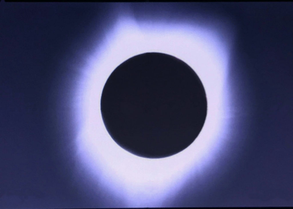
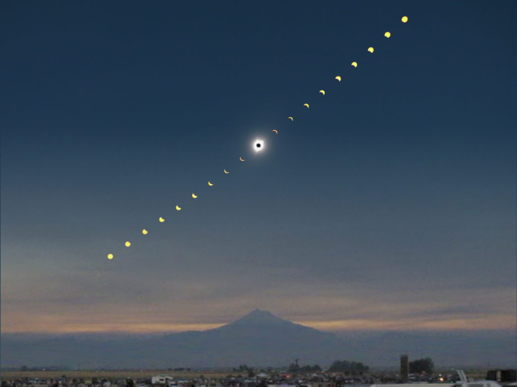
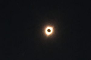
Bowing to the awesome spectacle that is a solar eclipse, this observer, together with his extended family and countless thousands of other umbraphiles, witnessed the awe-inspiring beauty that is this rare natural event. Despite the wildfires raging nearby, we were treated to near-perfect sky conditions in the high desert surrounding Madras, OR, a normally-modest town of just over 6,000 residents — which blossomed to possibly 30,000 or more in the days preceding the August 21 event.

Fires raging, north of Madras, OR

As the partial phases progressed, the crowd delighted in witnessing the transformation of the environment into an alien, bizarre landscape.  Shadows took on new, unfamiliar characteristics, with even one’s own fingers creating pinhole images of the the crescent sun.

Close-up shots showed the moon’s silhouette encroaching on a sunspot-adorned image of the sun’s disc.

Moon encroaching on the sun, Questar 3.5 w/ 100mm focal reducer

Then, finally, amid cheers from the crowd, the piÚce de résistance.

Total eclipse at Madras, OR, 10:20:35 AM PDT

While photographic techniques have evolved vastly in the past few decades, nothing can truly portray the personal experience at such an event.  To anyone who has seen a total eclipse, it is obvious that the difference between “99%” and “100%” is orders of magnitude greater than the mathematical “1%.”

Nonetheless, here is an attempt to capture the timeline of the event.  Allowing for artistic license, this picture combines different views of the eclipse, taken from the SolarFest “Solartown” campground.

Time-lapse sequence/montage of solar eclipse and Mt. Jefferson (in shadow), at Madras, OR

To some, the two minutes and five seconds of totality – replete with a 360° sunset-like horizon – lasted a lifetime; to others, it was over in a brief instant.  But even a novice could capture what could be a once-in-a-lifetime record of the event.

Eclipse shot by Sammi Dehen, Canon camera w/ 50mm lens

And then, it was all over.  (For a 15x time-lapse video of the shadow approaching and passing by, click here.) The die-hards remained in place until the last moments of exiting partial phase, while the novices departed seconds after totality ended.  Even the normally-quiet VFR-only S33 Madras municipal airport – which brought in a mobile control tower to handle the increased traffic – suddenly roared to life as opportune aristocrats jetted out from their brief two-hour stay.

Cugnini family (et al) at the levee, Solartown campground, Madras
Dehen family at the eclipse

This was the second total eclipse that I have witnessed (the first in Cabo San Lucas, Mexico, 1991), and both times, I was struck by the humbling experience of an earth – and solar system, and universe – of which we are such a small, but influential part. Nature and physics plod on, despite our meddling interference; may we be wise (and generous) enough to be a constructive part of this grand scheme.

— Aldo Cugnini

Photo credits: Aldo Cugnini, Charlotte Cugnini, Elizabeth Cugnini, Sam Dehen.

FCC Circulates NPRM to Authorize “Next Generation” Broadcast Television

THE FCC has pre-released a Notice of Proposed Rulemaking (NPRM), supporting the authorization of television broadcasters to use the “Next Generation” broadcast television (Next Gen TV) transmission standard developed by the Advanced Television Systems Committee (“ATSC 3.0”). They support a voluntary, market-driven basis, while broadcasters continue to deliver current-generation digital television (DTV) broadcast service, using the ATSC A/53 standard.

ATSC 3.0 is being developed by broadcasters with the intent of merging the capabilities of over-the-air (OTA) broadcasting with the broadband viewing and information delivery methods of the Internet, using the same 6 MHz channels presently allocated for DTV.

A coalition of broadcast and consumer electronics industry representatives has petitioned the Commission to authorize the use of ATSC 3.0, saying this new standard has the potential to greatly improve broadcast signal reception, particularly on mobile devices and television receivers without outdoor antennas, and that it will enable broadcasters to offer enhanced and innovative new features to consumers, including Ultra High Definition (UHD) picture and immersive audio, more localized programming content, an advanced emergency alert system (EAS) capable of waking up sleeping devices to warn consumers of imminent emergencies, better accessibility options, and interactive services.

With this action, the FCC says its aim is “to facilitate private sector innovation and promote American leadership in the global broadcast industry.” This document has been circulated for tentative consideration by the Commission at its open meeting on February 23. FCC Chairman Ajit Pai has determined that, in the interest of promoting the public’s ability to understand the nature and scope of issues under consideration by the Commission, the public interest would be served by making this document publicly available before officially requesting public comment.

ATSC Developing Conformance Testing Programs to Support Implementation of Next-Gen TV

630_ATSC-logo

Goal is to Assure Quality Consumer Experience,
Interoperability Between Next-Gen Receivers and Broadcast Content

WASHINGTON, Oct. 10, 2016 – The Advanced Television Systems Committee (ATSC) has issued a Request for Information (RFI) related to the development of Conformance Test Suite Development and Conformity Assessment programs to support the implementation of the ATSC 3.0 next-generation television broadcast standard.

According to ATSC President Mark Richer, the high-level goals of these programs include assuring a quality experience for consumers when viewing and interacting with ATSC 3.0 content, and assuring interoperability between broadcast content and receivers.

“The ATSC expects TV stations to begin testing in earnest in 2017, with early U.S. market deployments in the first half of 2018. To help achieve the highest quality user experience and to assure interoperability, the ATSC and other industry groups have a keen interest in the development of test suites and tools,” Richer said.

The RFI seeks input from industry experts in four areas of testing — Coding, Transmission & Reception; Data & Metadata; and Interactivity; and Security.  Specifically, the RFI addresses test suites, test automation, version management, test result formats and administration. The RFI also focuses on program management, including policy and procedure development and third-party assessment plans, as well as implementation tools and experience.

Richer explained that the RFI responses will inform the ATSC and allied organizations as they establish a framework, including initial plans and high-level budgeting, for the conformity assessment program.  It is expected the program will eventually be administered under the auspices of one or more industry organizations.

Current planning and technical work for ATSC 3.0 is focused on Internet Protocol-based service delivery and lays the foundation for improved viewing features, such as 4K Ultra HD, targeted advertising, high dynamic range and mobile/portable reception. ATSC 3.0 provides broadcasters the opportunity to deliver an enhanced viewing experience with interactive applications and program guides, including access to pre-cached video for later playback by viewers.

# # #

About the ATSC:
The Advanced Television Systems Committee is defining the future of television with the ATSC 3.0 next-generation broadcast standard.   ATSC is an international, non-profit organization developing voluntary standards for digital television. The ATSC’s 140-plus member organizations represent the broadcast, broadcast equipment, motion picture, consumer electronics, computer, cable, satellite, and semiconductor industries. For more information visit www.atsc.org.

A Few Thoughts About 4K Resolution

Ultra-HD and 4K TVs are quickly coming down in price, and manufacturers are pushing them as “the next big thing.”  Is it worth upgrading?  A central issue here is, can the typical consumer notice the difference?  It all has to do with how far you set from the display, as this will limit one’s ability to perceive small detail.

800px-Snellen_chart.svg
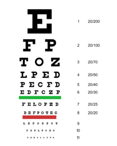
So what is the practical viewing distance for a display? People with “20/20” vision have a visual acuity that can resolve 60 features per degree, or 30 cycles per degree. From this, we can calculate that the “optimum” distance from which to observe a 1080-line display is about 3.2 times the picture height, where the vertical viewing angle is 18 degrees. Further than that, and a person with 20/20 corrected vision can’t resolve the smallest displayed details; closer than that, and you’ll start to see individual pixels.

Stated in screen diagonals, this works out to 1.55 times the diagonal measure of a 1920×1080 display.  For a 1080-line display with 42” diagonal, the optimum viewing distance works out to be about five-and-a-half feet.

But at 4K resolution, in order to resolve 30 cycles per degree, the optimum distance becomes about 1.5 picture heights, or about 0.75 screen diagonals. For an 84” set, that means sitting at about 5.3 feet from the screen — a truly immersive experience, as the horizontal angle subtended by the display would be about 60 degrees, or about half of the normal binocular range of human vision.

Funny enough (or is it?), the 84-inch Sony Bravia is said to have a viewing angle of just that: 60 degrees. But at a smaller screen size, like 42″, the optimum distance is just 32 inches, which is not at all practical, unless you plan to use that as an ultra-large computer monitor.

These calculations assume that there are no other limiting conditions; in reality, factors based on Kell factor, interlace, the inter-pixel grid, contrast and the sharp edges of image details must all be taken into account. Also, because most people view their TV from a larger distance of about 9 feet (the so-called “Lechner distance,” named after RCA researcher Bernie Lechner), the required optimum screen size grows proportionally.

NHK researchers wrote in a 2008 paper that test subjects could distinguish between images with effective resolutions of 78 and 156 cycles per degree. This suggests that some people can tell the difference between a display with 1080 lines and one with 2160 lines, when viewed within the practical confines of a living room.

Of course, 4K sets come bundled with other features that exceed the capability of HD sets, like 60 fps (or higher), and 10-bit color – with 12-bit on the way.  Just emerging, too, are sets with High Dynamic Range (HDR), which provides an improvement in perception of reality that, in many cases, can exceed that of 4K alone.

Time to get a bigger house?

–agc