This is one of my engineering pet peeves — I keep running into students and (false) advertisements that describe a power output in “RMS watts.” The fact is, such a construct, while mathematically possible, has no meaning or relevance in engineering. Power is measured in watts, and while the concepts of average and peak watts are tenable, “RMS power” is a fallacy. Here’s why.
The power dissipated by a resistive load is equal to the square of the voltage across the load, divided by the resistance of the load. Mathematically, this is expressed as [Eq.1]:
\large P=\frac{V^{2}}{R}
where P is the power in watts, V is the voltage in volts, and R is the resistance in ohms. When we have a DC signal, calculating the power in the load is straightforward. The complication arises when we have a time-varying signal, such as an alternating current (AC), e.g, an audio signal or an RF signal. In the case of power, the most elementary time-varying function involved is the sine function.
When measuring the power dissipated in a load carrying an AC signal, we have different ways of measuring that power. One is the instantaneous or time-varying power, which is Equation 1 applied all along the sinusoid as a time-varying function. (We will take R = 1 here, as a way of simplifying the discussion; in practice, we would use an appropriate value, e.g., 50Ω in the case of an RF load.)

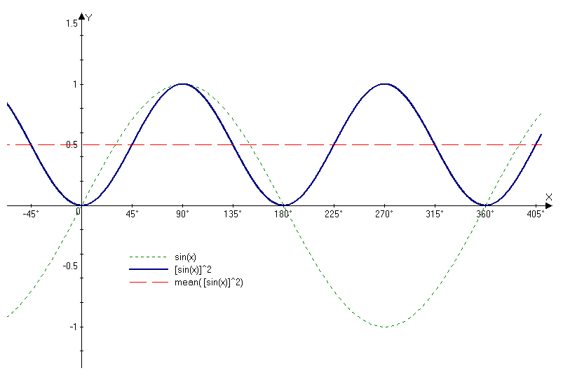
In Figure 1, the dotted line (green) trace is our 1-volt (peak) sinusoid. (The horizontal axis is in degrees.) The square of this function (the power as a function of time) is the dark blue trace, which is essentially a “raised cosine” function. Since the square is always a positive number, we see that the instantaneous power as a function of time rises and falls as a sinusoid, at twice the frequency of the original voltage. This function itself has relatively little use in most applications.
Another quantity is the peak power, which is simply Equation 1 above, where V is taken to be the peak value of the sinusoid, in this case, 1. This is also known as peak instantaneous power (not to be confused with peak envelope power, or PEP). The peak instantaneous power is useful to understand certain limitations of electronic devices, and is expressed as follows:
\large P_{pk}=\frac{V^{2}_{pk}}{R}
A more useful quantity is the average power, which will provide the equivalent heating factor in a resistive device. This is calculated by taking the mean (i.e., the average) of the square of the voltage signal, divided by the resistance. Since the sinusoidal power function is symmetric about its vertical midpoint, simple inspection (see Figure 1 again) tells us that the mean value is equal to one-half of the peak power [Eq.2]:
\large P_{avg}=\frac{P_{pk}}{2}=\frac{V^{2}_{pk}/R}{2}
which in this case is equal to 0.5. We can see this in Figure 1, where the average of the blue trace is the dashed red trace. Thus, our example of a one-volt-peak sinusoid across a one-ohm resistor will result in an average power of 0.5 watts.
Now the concept of “RMS” comes in, which stands for “root-mean-square,” i.e., the square-root of the mean of the square of a function. The purpose of RMS is to present a particular statistical property of that function. In our case, we want to associate a “constant” value with a time-varying function, one that provides a way of describing the “DC-equivalent heating factor” of a sinusoidal signal.
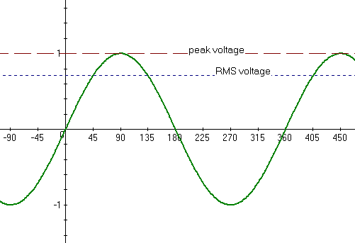
Taking the square-root of V2pk/2 therefore provides us with the root-mean-square voltage (not power) across the resistor; in this example, that means that the 1-volt (peak) sinusoid has an RMS voltage of
\large V_{rms}=\sqrt{\frac{V^{2}_{pk}}{2}}=\frac{V_{pk}}{\sqrt{2}}\approx 0.7071
Thus, if we applied a DC voltage of 0.7071 volts across a 1Ω resistor, it would consume the same power (i.e., dissipate the same heat) as an AC voltage of 1 volt peak (0.7071 volts RMS). (Note that the RMS voltage does not depend on the value of the resistance, it is simply related to the peak voltage of the sinusoidal signal.) Plugging this back into Eq. 2 then gives us:
\large P_{avg}=\frac{V^{2}_{rms}}{R}
Note the RMS voltage is used to calculate the average power. As a rule, then, we can calculate the RMS voltage of a sinusoid this way:
\large V_{rms} \approx 0.7071 \cdot V_{pk}
Graphically, we can see this in Figure 2:

The astute observer will note that 0.7071 is the value of sin 45° to four places. This is not a coincidence, but we leave it to the reader to figure out why. Note that for more complex signals, the 0.7071 factor no longer holds. A triangle wave, for example, yields Vrms ≈ 0.5774 · Vpk , where 0.5774 is the value of tan 30° to four places.
For those familiar with calculus, the root-mean-square of an arbitrary function f(t) is defined as:
\large F_{rms} = \sqrt{\frac{1}{T_{2}-T_{1}}\int_{T_{1}}^{T_{2}}[f(t)]^{2}\, dt}
Replacing f(t) with sin(t) (or an appropriate function for a triangle wave) will produce the numerical results we derived above.
For more information on the root-mean-square concept, see the Wikipedia articles Root mean square and Audio power.
Additional thoughts on root-mean-square
Because of the squaring function, one may get the sense that RMS is only relevant for functions that go positive and negative, but this is not true.
RMS can be applied to any set of distributed values, including only-positive ones. Take, for example, the RMS of a rectified (i.e., the absolute value of a) sine wave. As before, Vrms=0.7071 · Vpk , i.e., the RMS is the same as for the full-wave case. However, Vavg ≈ 0.6366 · Vpk for the rectified wave (but equals zero for the full-wave, of course, and 0.6366 is the value of 2/π to four places). So, we can take the RMS of a positive-only function, and it can be different than the average of that function.
The general purpose of the RMS function is to calculate a statistical property of a set of data (such as a time-varying signal). So the application is not just to positive-going data, but to any data that varies over the set.
—agc